Please choose your delivery location

The selection of the country/region page can influence various factors such as price, shipping options and product availability.
My contact person
e-chains®, chainflex®, cables, harnessed systems readychain®

Alaa Abdelaziz

+202 25767370
Photo
dry-tech® bearing technology

Alaa Abdelaziz

+202 25767370
Photo
EG(EN)

Energy chains for an XXL 3D water jet cutting machine

An unsupported energy supply system with a travel of 32m is durable despite chips.

With a travel of 32 metres (X-axis) by 5 metres (Y-axis), the double 3D water jet cutting machine H. G. Ridder Automatisierungs GmbH planned and built for the new Anssems Group plant has impressive dimensions. So does its energy supply systems. They create an important prerequisite for the precise movement of the two 3D cutting heads on the linear robot axes.

Profile

  • What was needed: E4.1-series polymer energy chainchainflex energy cablesCAN bus cables,  guidelok system for energy chains
  • Requirements: The cutting heads were to be reliably supplied with energy, signals, compressed air, and water over a 32m travel at a max. speed of 20m/min. Friction and chips meant that the upper run could not glide on the lower run.
  • Industry: Machine tools
  • Success for the customer: The guidelok system was able to ensure stable upper run guidance with just a few components and a simple mechanism. The chain's service life increases, and chips cannot damage it.
Discover all products for machine tools
Water jet cutting machine Impressive size: external view of the Anssems water jet cutting machine.

Products used

Problem

Ridder is known as a water jet cutting specialist: Water jets deliver an almost unimaginable pressure (3,800 bar) to separate metals and plastics. The advantages of the "cold" process are that no harmful emissions develop during cutting and that the cutting surface is given a perfect finish even without rework. And there is no distortion in the cutting.
Ridder originally developed systems with a cutting table for 2D machining. Later, Waricut-series 3D linear robot systems that moved on vertical axes were added. But this is the largest machine that Ridder has put into operation to date:
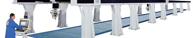
The Anssems Group, based in the Netherlands, has ordered a five-axis water jet cutting machine with a cutting volume of 32,050 x 5,050 x 1,900mm (X/Y/Z axis) for horse trailer production. Two bridges, each with a 3D cutting head, move on 32-metre linear robot axes. The machine is divided into four cabins so that the two cutting heads can each process one component while the other two cabins are being changed over. This ensures continuous system utilisation. Each cutting head can move to all four cabins, ensuring high flexibility and availability.
The water jet cutting machine's task in production will be to process the glass-fibre reinforced plastic superstructures that were laminated and formed in the previous work steps and make door cut-outs in the horse trailer, for instance. It achieves very high precision. While the systems usually work with an accuracy of ≤ ± 20µm per metre, the long travels mean that this system has an accuracy of 50µm. The Ridder design engineers had to solve the problem of supplying the cutting heads with energy, signals, compressed air, and (of course) water. The high linear axis maximum travel speeds (20m/min) also had to be taken into account. But the biggest problem was the long travel. Given these lengths, the chain's upper run is especially likely to simply rest on the lower run (the gliding energy chain principle). This system could not thus glide for two reasons: The heavy filling and long travel distance would have generated too much friction. And the high-pressure line for the water supply requires a larger bend radius, so the "chain on chain" principle was out of the question.

Solution

The design engineers opted for a solution that had already proven itself in other Ridder systems: an E4.1-series polymer energy chain. The energy chain is used with a width of 100mm and a height of 56mm. In addition to the high-pressure line with a ¼ inch diameter, the chainflex power cables for the 3D cutting head and the CAN bus cables for communication, which are specifically for continuous use, are also guided in it. A central crossbar ensures that the high-pressure line is reliably separated from the electrical cables. To keep the two chains as short as possible with a travel of 32 metres, the feed is in the middle of the travel.
But a solution to the falling chain problem was also needed. If chips can accumulate on the upper side of the lower run, the gliding principle must be abandoned because the chips can damage the chain parts that glide on each other. The guidelok system for energy chains was developed for such cases. It allows independent guidance of the upper run. It consists of paired support elements in which pivoting roller brackets are mounted. As the chain is fed past the supports, the roller brackets pivot inwards and then outwards again to guide the chain. The upper run thus rests on the roller bracket, maintaining its distance to the lower run. Another advantage of this principle is that the chain bend radius can be freely determined: It is simply results from the height at which the roller brackets are mounted.
Very strong upper run guidance can thus be ensured with a very simple mechanism and few components – and the unsupported energy chain lengths greatly increased. Because the chain is guided with rollers in the guidelok system, very little push/pull force is required to move it – ensuring that the chain runs smoothly and energy-efficiently.
The test results have now also confirmed system performance. When the system starts operation, several devices with trailer superstructures are precisely positioned in a cabin, and a 3D CAD/CAM program allows fully automatic processing of these glass-fibre reinforced plastic superstructures. The moving cutting head, which can pivot by ± 95° and rotate by ± 540°, allows cutting even in hard-to-reach areas. And while the system is working through its programs in two cabins, the other two can be fitted with new components.
chainflex cable feed The feed is in the centre of the travel.
guidelok guidelok from inside and outside: The roller brackets swing out only when there is a chain in the guidance system.
Energy chain The guidelok system also ensures that the defined bend radius is not exceeded. On the left in the chain, the 3,800-bar high-pressure hose line is visible.
Energy chain The large chain filling was another reason for using the guidelok system.
Concept drawing of a Waricut raised gantry plant. Concept drawing of a Waricut raised gantry plant. On Anssems' plant, the 3D cutting heads cover an area of 32 x 5 meters (x/y axis).

More info

Used products

Application examples:


Consulting

I look forward to answering your questions

Shipping and consultation

In person:

Monday to Friday from 7 am - 8 pm.
Saturdays from 8 am- 12 pm.

Online:

24h


The terms "igus", "Apiro", "chainflex", "CFRIP", "conprotect", "CTD", "drylin", "dry-tech", "dryspin", "easy chain", "e-chain", "e-chain systems", "e-ketten", "e-kettensysteme", "e-skin", "e-spool", "flizz", "ibow", "igear", "iglidur", "igubal", "igutex", "kineKIT", "manus", "motion plastics", "pikchain", "readychain", "readycable", "ReBeL", "speedigus", "triflex", "robolink", "xirodur", and "xiros" are legally protected trademarks of the igus® GmbH/ Cologne in the Federal Republic of Germany and where applicable in some foreign countries.

igus® GmbH points out that it does not sell any products of the companies Allen Bradley, B&R, Baumüller, Beckhoff, Lahr, Control Techniques, Danaher Motion, ELAU, FAGOR, FANUC, Festo, Heidenhain, Jetter, Lenze, LinMot, LTi DRiVES, Mitsubishi, NUM,Parker, Bosch Rexroth, SEW, Siemens, Stöber and all other drive manufacturers mention on this website. The products offered by igus® are those of igus® GmbH